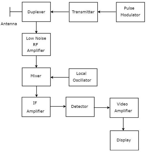
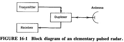
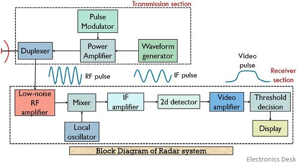
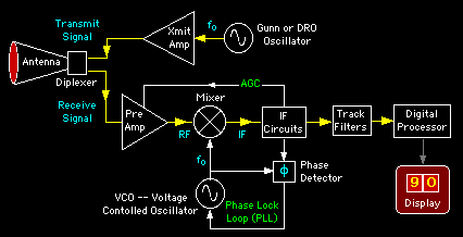
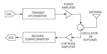
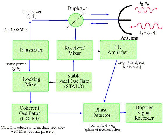
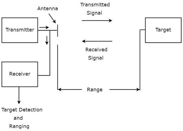
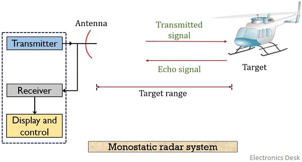
Radar System Block Diagram
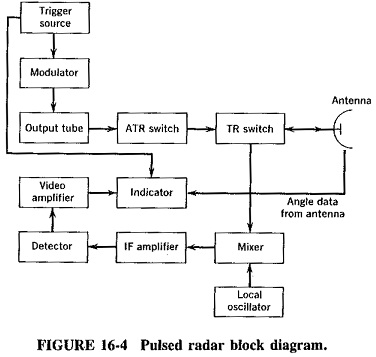
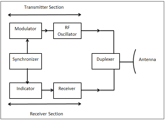
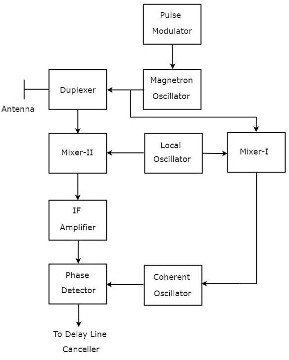
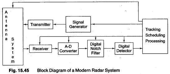
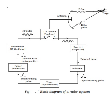
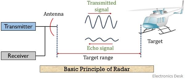
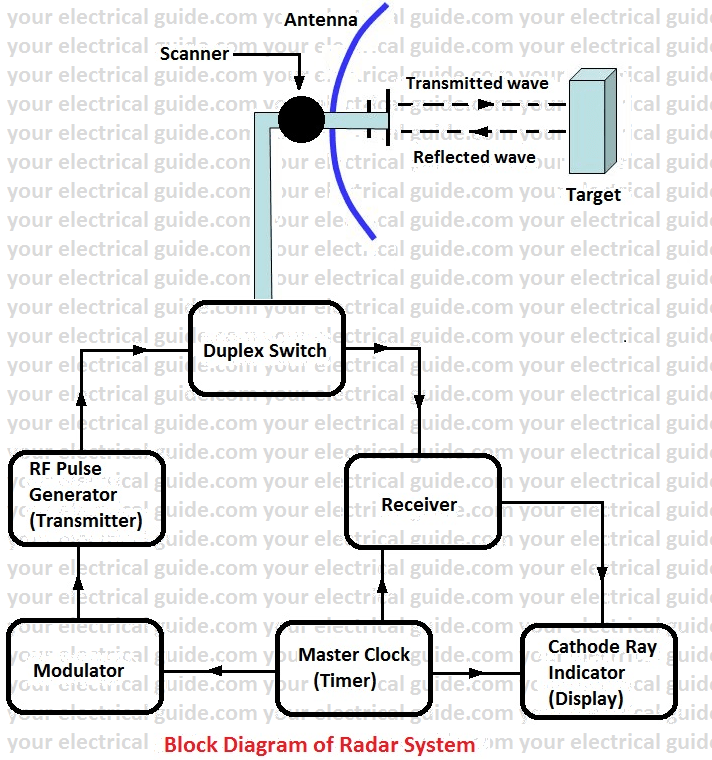
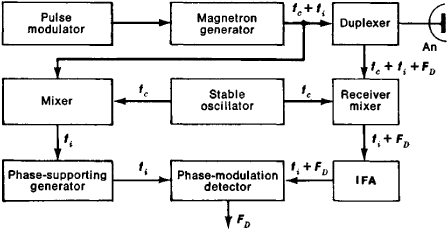
Radar system block diagram. Block 1 baseline 1 replaced the hydraulic gun drive with a pneumatic air-driven gun drive system that increased the rate of fire to 4500 rounds per minute. An automatic ship and ship wake detection system for spaceborne SAR images in coastal regions. Here the following equation is one of the fundamental types for an only antenna system.
The power converters change one form of electric power into some other form with the use of a power semiconductor device. Amazon Fire TV Stick 4K Max review. Windows 11 is the latest operating system from Microsoft and while it gets a lot right theres still work to be done.
When the object is assumed to be in the middle of the antenna signal then the highest radar detection range can be written as. Block Diagram Showing CW RADAR Radar Range Equation. The figure below represents the block diagram of a power electronics-based system.
These codes are often implemented in concatenation with a hard-decision code particularly ReedSolomon. Convolutional codes are used extensively to achieve reliable data transfer in numerous applications such as digital video radio mobile communications eg in GSM GPRS EDGE and 3G networks until 3GPP Release 7 and satellite communications. 100-D random noise vector z z 1 z 2 z 100 T obeying a uniform distribution into the front-end deconvolution block G1.
There are different kinds of versions available for the radar range equations. Synthetic aperture radar. During these times in the millisecond range the radar will work as for CW radar method.
Secondary surveillance radar SSR is a radar system used in air traffic control ATC that unlike primary radar systems that measure the bearing and distance of targets using the detected reflections of radio signals relies on targets equipped with a radar transponder that reply to each interrogation signal by transmitting encoded data such as an identity code the aircrafts altitude and. As it is clear from the above figure that here we are having a power electronics converter and controller along with some interfacing units. The output of the down mixer see block diagram a DC voltage appears as a measure of the phase difference between the reception signal and its transmission signal.
The discriminator D consists of seven Conv blocks D1 D2.
The power converters change one form of electric power into some other form with the use of a power semiconductor device.
Secondary surveillance radar SSR is a radar system used in air traffic control ATC that unlike primary radar systems that measure the bearing and distance of targets using the detected reflections of radio signals relies on targets equipped with a radar transponder that reply to each interrogation signal by transmitting encoded data such as an identity code the aircrafts altitude and. An automatic ship and ship wake detection system for spaceborne SAR images in coastal regions. The figure below represents the block diagram of a power electronics-based system. Convolutional codes are used extensively to achieve reliable data transfer in numerous applications such as digital video radio mobile communications eg in GSM GPRS EDGE and 3G networks until 3GPP Release 7 and satellite communications. 100-D random noise vector z z 1 z 2 z 100 T obeying a uniform distribution into the front-end deconvolution block G1. When the object is assumed to be in the middle of the antenna signal then the highest radar detection range can be written as. Block 1 baseline 1 replaced the hydraulic gun drive with a pneumatic air-driven gun drive system that increased the rate of fire to 4500 rounds per minute. Here the following equation is one of the fundamental types for an only antenna system. The power converters change one form of electric power into some other form with the use of a power semiconductor device.
Block 1 baseline 1 replaced the hydraulic gun drive with a pneumatic air-driven gun drive system that increased the rate of fire to 4500 rounds per minute. During these times in the millisecond range the radar will work as for CW radar method. There are different kinds of versions available for the radar range equations. As it is clear from the above figure that here we are having a power electronics converter and controller along with some interfacing units. The figure below represents the block diagram of a power electronics-based system. These codes are often implemented in concatenation with a hard-decision code particularly ReedSolomon. Block 1 baseline 1 replaced the hydraulic gun drive with a pneumatic air-driven gun drive system that increased the rate of fire to 4500 rounds per minute.


















Post a Comment for "Radar System Block Diagram"